Applications
- Small cold rooms
- Commercial refrigeration cold rooms
Capacity Range
From 1 to 27,2 kW
Download
EMEA:
Commercial Coolers General Catalog (English, German, Russian)
Commercial Coolers General Catalog (Italian, French, Spanish)
Commercial Coolers Product Overview Brochure
CO2 Commercial Coolers Product Overview Brochure
Technical Manual
Declaration Of Incorporation – Test Certificate
Quick Guide
APAC:
Technical Manual
CGC Specifications
Overview
Range consists of 105 customizable models.
According to the cold room temperatures, the range is divided as follows:
- CGC G4 E4 F4 A4 for higher temperatures (≥ +2 °C) with 4 mm fin spacing
- CGC G6 E6 F6 A6 or medium temperatures (≥ –15 °C) with 6 mm fin spacing, electric defrost version (ED) is recommended
- CGC G8 E8 F8 A8 for low temperatures (≥ –35 °C) with 8 mm fin spacing, equipped with electric defrost (ED)
On request, the models can be equipped with non-standard: coils, defrosting, and fan motors.
Coil Features
- This new range is equipped with highly efficient coils made from aluminum fins and special copper tubes
- Maximum allowable pressure: 80 bar
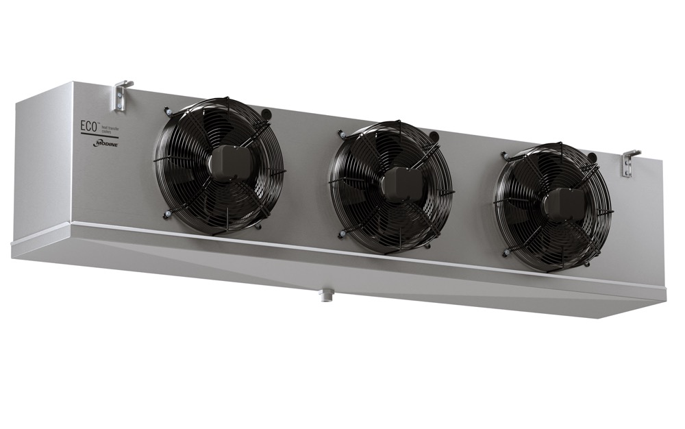
Casing
Casing Features
Made of a magnesium aluminum alloy, with a smooth finish covered by a plastic protection film
Fan Motors
The standard AC fan motors employed have the following features:
The optional high efficiency EC fan motors have the following features:
- Ø 250 mm:
- fan motor module: from 1 to 4
- shaded pole single-phase 230V/1/50-60Hz
- fibreglass charged polyamide fan guards
- Ø 315 mm:
- fan motor module: from 2 to 4
- external rotor single-phase 230V/1/50-60Hz
- built-in electric capacitor
- epoxy coated steel fan guard
- Ø 350 mm:
- fan motor module: from 1 to 5
- shaded pole single-phase 230V/1/50-60Hz
- built-in electric capacitor
- epoxy coated steel fan guard
The optional high efficiency EC fan motors have the following features:
- Ø 250 mm:
- fan motor module: the same as AC fan motors
- 230V/1/50-60Hz
- fiberglass charged polyamide fan guards
- Ø 315 mm:
- fan motor module: the same as AC fan motors
- external rotor single-phase 230V/1/50-60Hz
- epoxy coated steel fan guard
- Ø 350 mm:
- fan motor module: the same as AC fan motors
- shaded pole single-phase 230V/1/50-60Hz
- epoxy coated steel fan guard
Defrost
The electric defrost (ED) versions are equipped with stainless steel heaters with vulcanised terminals preset for 400V/3/50-60Hz connections
Wiring
- The electric parts and casing are connected to an earth terminal
- The wiring of motors and heaters is carried out in separate IP 54 protection grade junction boxes
Certifications
- CE
- PED
Published Data
Nominal capacity assessed in practical operating ambient, i.e. in wet conditions, in direct expansion application
- CGC Fin spacing code 4: CO2 refrigerant; air inlet temperature 4 °C; evaporating temperature –4 °C; TD 8 K
- CGC Fin spacing code 6: CO2 refrigerant; air inlet temperature 0 °C; evaporating temperature –8 °C; TD 8 K
- CGC Fin spacing code 8: CO2 refrigerant; air inlet temperature –25 °C; evaporating temperature –33 °C; TD 8 K